
New combi Boiler System Central Heating job in Gillingham, Kent MyBuilder
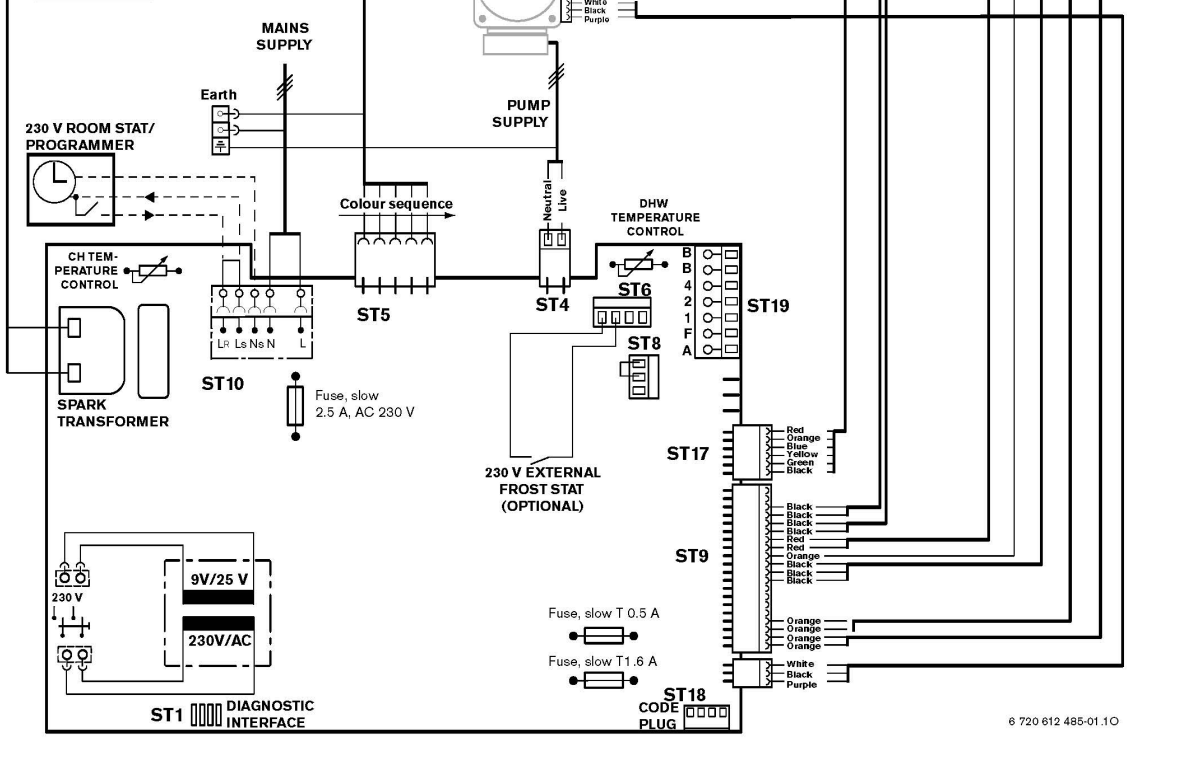
S Plan Boiler Connections S Plan boiler wiring diagram with pump overrun, shown below 몭 rst is the cable (function) followed by the terminal number of the wiring centre. Live = 1 Earth = 2 09/04/2023 procertssotftware.com 3DJH RI Megger MFT1741 Multifunction Tester Fluke T130 Voltage and
Worcester Combi Boiler Wiring Diagram Homemadeist
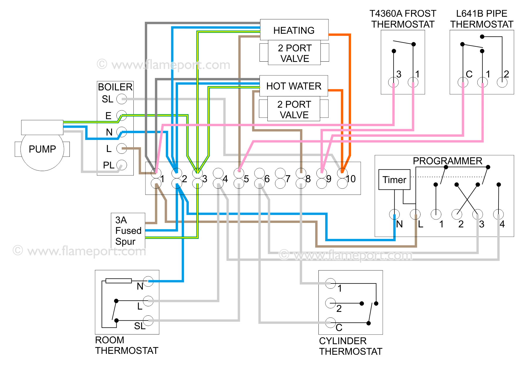
Wiring diagrams for two zone valves with a combination boiler that has 230V switching. Overview Video Combi Boiler with Two Heating Zones, 230V Switching Watch on This video covers the basic plumbing arrangement for the valves, and a detailed explanation of the wiring for the valves, boiler and thermostats. View on Youtube.

Luxury Wiring Diagram Combi Boiler diagrams digramssample diagramimages wiringdiagramsample
Y Plan. Wiring for Y plan is almost identical - the only difference is that the wire from the thermostat on terminal 5 connects to the white valve wire. The white wire selects heating, the valve moves to the heating position, and the boiler is activated via the orange output wire.. Combination boilers are all-in-one devices, and typically do.

Combination ( Combi ) Boiler perfect heating and plumbing
Combination Boiler with radiators & UFH 1b) Plumbing Schematic 2b) Multi Zone Wiring Schematic 3b) Single Zone Wiring Schematic Section C Adding Single Zone kit to exisiting radiator system 1c) Plumbing Schematic 2c) Wiring Schematic 3c) Plumbing Schematic (Danfoss kit) Section D H-Box-12 Wiring Schematics
Sale > combi boiler wiring diagram > in stock
#1 Hi. Does anyone please have any links for a wiring diagram for a new housing association home. It has a Baxi condensing boiler, 2 Zone valves and 2 separate Mysson MPRT programmable room thermostats. I'm assuming this is now a requirement to have upstairs and downstairs on separate zones. Many thanks, Alan ShaunCorbs Staff member S. Mod Plumber

Wiring Diagram For Wet Underfloor Heating Wiring Diagram Schemas
Electrically, the valve has 5 wires: Green/Yellow, Earth - connected to the metal body of the valve. Blue, Neutral - internally connected to the neutral side of the motor. Brown, Live in - Activates the motor inside the valve Grey - Connected to one side of a switch inside the valve.

Boiler Wiring Diagram Wiring Diagram Schematic
Principle of operation A combination boiler, or combi, is a boiler which heats hot water on demand, and additionally can function as a normal boiler to heat hot water for radiators. There are no controls for the hot water section - hot taps are plumbed directly to the boiler.
Boiler wiring DIYnot Forums
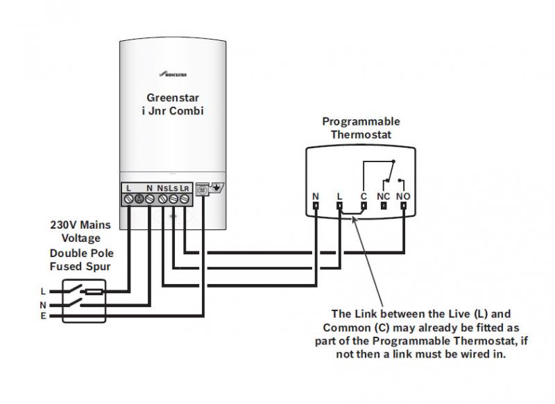
Combination boilers and connecting thermostats to them, including Hive and Nest. Also covers volt free contacts and why mains voltage must not be connected.

Wiring Diagram For Y Plan Wiring Diagram and Schematics
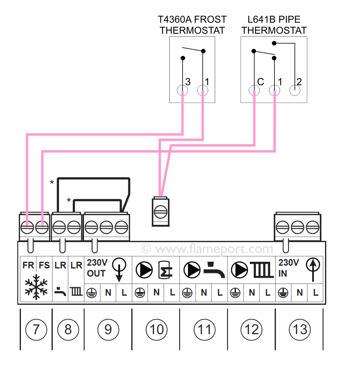
Combination Boiler with Two Heating Zones - Universal. Wiring diagrams for two zone valves with a combination boiler. This can be used with any boiler control voltage including 24V, volt free, 230V and others. The difference is that the zone valve switch is used to connect two terminals in the boiler together, rather than connecting 230V to one.
Vaillant Ecotec 831 combi on 2 zone heating system
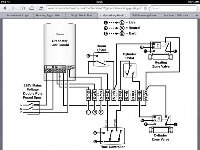
Wiring Diagrams Wiring Diagrams Current products Search by boiler type Combi Boilers System Boilers Regular Boilers Greenstar CDi Compact Wiring Diagram Internal View Gas Combi Show Product Greenstar CDi Highflow Wiring Diagram Internal View Gas Combi Show Product Greenstar Heatslave II Wiring Diagram Internal View Oil Combi Show Product

Wiring Plan for Fireplace Boiler Twinsprings Research Institute
6 to 8 hours Combi Boiler Installation in 10 Steps: Mount a plywood panel to the basement wall to serve as a mounting panel for the new combination boiler. Run new gas, electrical, and plumbing lines to the plywood panel. Screw the metal mounting brackets to the plywood panel, then hang the combination heater onto the brackets.
Central Heating Room Thermostat Wiring
NFC-H Combi-Boiler Application - Two Pipe Reverse Return with Manifold Kit Part #30026576B. NFC-H Combi-Boiler Application with Single Circulator with AHU Shown wtih Manifold Kit Part #30026576B. NFC-H Combi-Boiler with Multiple System Zone Valves Shown with Manifold Kit Part #30026576B.

WIRING DIAGRAM FOR VAILLANT ECOTEC PLUS Diagram
Standard 's' plan set up with two heating instead of heating and hot water. Both oranges connected together as switched live to boiler enables either zone to fire the boiler when it's respective room stat calls for heat. The second zone valve will not operate due to having a 'backfeed' up the orange. Hope that makes sense.
Worcester Combi Boiler Wiring Diagram Homemadeist
Wiring for a combination boiler with two central heating zones, each zone controlled by its own thermostat.This shows two methods of switching the boiler usi. Wiring for a combination.
2 channel thermostat to combi boiler DIYnot Forums
Condensing combi-boilers deliver high-efficiency endless hot water and space heating in one compact unit. Overview Condensing combi-boilers > NCB‑H Series > NFC‑H Series Boilers Space-saving high-efficiency condensing boilers provide the ultimate home heating and comfort experience. Overview Condensing heating boilers
Under Floor Heating Wiring
Not combi boilers. System boilers. system boilers do heating and a hot water tank. y plan for systems with a3 port valve s plan for system with two 2 port valves. just google it loads of images pop up.